第12章静的つり合いと弾性
12.1 Conditions for Static Equilibrium12.1 静的つり合いの条件
Learning Objectives学習目標
Learning Objectives学習目標
By the end of this section, you will be able to:
英語のヒント
この節を終えると、次のことができるようになる。
- Identify the physical conditions of static equilibrium.
英語のヒント
静的つり合いの物理的な条件を特定する。 - Draw a free-body diagram for a rigid body acted on by forces.
英語のヒント
力を受ける剛体の力の図を描く。 - Explain how the conditions for equilibrium allow us to solve statics problems.
英語のヒント
つり合いの条件によって、静力学の問題をどのように解けるかを説明する。
We say that a rigid body is in equilibrium when both its linear and angular acceleration are zero relative to an inertial frame of reference. This means that a body in equilibrium can be moving, but if so, its linear and angular velocities must be constant. We say that a rigid body is in static equilibrium when it is at rest in our selected frame of reference. Notice that the distinction between the state of rest and a state of uniform motion is artificial—that is, an object may be at rest in our selected frame of reference, yet to an observer moving at constant velocity relative to our frame, the same object appears to be in uniform motion with constant velocity. Because the motion is relative, what is in static equilibrium to us is in dynamic equilibrium to the moving observer, and vice versa. Since the laws of physics are identical for all inertial reference frames, in an inertial frame of reference, there is no distinction between static equilibrium and equilibrium.
英語のヒント
慣性基準系に対して、剛体の直線加速度と角加速度がともにゼロであるとき、剛体はつり合いにあるという。つり合っていても動くことはできるが、その場合、直線速度と角速度は一定でなければならない。選んだ基準系で静止していれば、静的つり合いにあるという。静止と等速運動の区別は、基準系の選び方による。ある基準系で静止する物体も、それに対して一定速度で動く観測者には、一定速度で等速運動して見える。運動は相対的なので、私たちにとっての静的つり合いは、動く観測者にとっての動的つり合いとなり、逆も成り立つ。物理法則はすべての慣性基準系で同じなので、慣性基準系では、静的つり合いとつり合いを本質的に区別することはない。
According to Newton’s second law of motion, the linear acceleration of a rigid body is caused by a net force acting on it, or
英語のヒント
ニュートンの運動の第2法則によれば、剛体の直線加速度は、剛体に働く合力によって生じる。すなわち、
(12.1)
Here, the sum is of all external forces acting on the body, where m is its mass and is the linear acceleration of its center of mass (a concept we discussed in Linear Momentum and Collisions on linear momentum and collisions). In equilibrium, the linear acceleration is zero. If we set the acceleration to zero in Equation 12.1, we obtain the following equation:
英語のヒント
The first equilibrium condition, Equation 12.2, is the equilibrium condition for forces, which we encountered when studying applications of Newton’s laws.
英語のヒント
つり合いの第1条件である式12.2は、ニュートンの法則の応用を学んだ際に出てきた、力のつり合いの条件である。
This vector equation is equivalent to the following three scalar equations for the components of the net force:
英語のヒント
このベクトルの式は、合力の成分についての次の三つのスカラー方程式と同値である。
(12.3)
Analogously to Equation 12.1, we can state that the rotational acceleration of a rigid body about a fixed axis of rotation is caused by the net torque acting on the body, or
英語のヒント
式12.1と同様に、固定軸の周りの剛体の角加速度は、剛体に働く合トルクによって生じると表せる。すなわち、
(12.4)
Here is the rotational inertia of the body in rotation about this axis and the summation is over all torques of external forces in Equation 12.2. In equilibrium, the rotational acceleration is zero. By setting to zero the right-hand side of Equation 12.4, we obtain the second equilibrium condition:
英語のヒント
The second equilibrium condition, Equation 12.5, is the equilibrium condition for torques that we encountered when we studied rotational dynamics. It is worth noting that this equation for equilibrium is generally valid for rotational equilibrium about any axis of rotation (fixed or otherwise). Again, this vector equation is equivalent to three scalar equations for the vector components of the net torque:
英語のヒント
つり合いの第2条件である式12.5は、回転の動力学で学んだトルクのつり合いの条件である。この式は一般に、回転軸が固定されているかどうかにかかわらず、どの軸の周りの回転のつり合いにも成り立つ。このベクトルの式も、合トルクの各成分についての三つのスカラー方程式と同値である。
(12.6)
The second equilibrium condition means that in equilibrium, there is no net external torque to cause rotation about any axis.
英語のヒント
つり合いの第2条件は、つり合いでは、どの軸の周りにも回転を引き起こす外力による合トルクが存在しないことを意味する。
The first and second equilibrium conditions are stated in a particular reference frame. The first condition involves only forces and is therefore independent of the origin of the reference frame. However, the second condition involves torque, which is defined as a cross product, where the position vector with respect to the axis of rotation of the point where the force is applied enters the equation. Therefore, torque depends on the location of the axis in the reference frame. However, when rotational and translational equilibrium conditions hold simultaneously in one frame of reference, then they also hold in any other inertial frame of reference, so that the net torque about any axis of rotation is still zero. The explanation for this is fairly straightforward.
英語のヒント
つり合いの第1条件と第2条件は、特定の基準系で表される。第1条件には力だけが現れるため、基準系の原点には依存しない。しかし第2条件には、外積で定義されるトルクが現れる。この式には、回転軸に対する力の作用点の位置ベクトルが入るため、トルクは基準系内での軸の位置に依存する。それでも、ある基準系で回転と並進のつり合いが同時に成り立てば、他のどの慣性基準系でも成り立ち、どの回転軸の周りの合トルクもゼロとなる。これは比較的簡単に説明できる。
Suppose vector is the position of the origin of a new inertial frame of reference in the old inertial frame of reference S. From our study of relative motion, we know that in the new frame of reference the position vector of the point where the force is applied is related to via the equation
英語のヒント
新しい慣性基準系の原点の、元の慣性基準系Sでの位置を、ベクトルとする。相対運動で学んだように、新しい基準系での力の作用点の位置ベクトルは、次式でと結び付く。
Now, we can sum all torques of all external forces in a new reference frame,
英語のヒント
新しい基準系で、すべての外力によるトルクの和を取る。
In the final step in this chain of reasoning, we used the fact that in equilibrium in the old frame of reference, S, the first term vanishes because of Equation 12.5 and the second term vanishes because of Equation 12.2. Hence, we see that the net torque in any inertial frame of reference is zero, provided that both conditions for equilibrium hold in an inertial frame of reference S.
英語のヒント
The practical implication of this is that when applying equilibrium conditions for a rigid body, we are free to choose any point as the origin of the reference frame. Our choice of reference frame is dictated by the physical specifics of the problem we are solving. In one frame of reference, the mathematical form of the equilibrium conditions may be quite complicated, whereas in another frame, the same conditions may have a simpler mathematical form that is easy to solve. The origin of a selected frame of reference is called the pivot point.
英語のヒント
実際の計算では、剛体につり合いの条件を適用するとき、基準系の原点をどの点に選んでもよいことを意味する。基準系は、解く問題の物理的な特徴に合わせて選ぶ。ある基準系ではつり合いの式が複雑でも、別の基準系では同じ条件を、簡単で解きやすい式にできる場合がある。選んだ基準系の原点を、支点と呼ぶ。
In the most general case, equilibrium conditions are expressed by the six scalar equations (Equation 12.3 and Equation 12.6). For planar equilibrium problems with rotation about a fixed axis, which we consider in this chapter, we can reduce the number of equations to three. The standard procedure is to adopt a frame of reference where the z-axis is the axis of rotation. With this choice of axis, the net torque has only a z-component, all forces that have non-zero torques lie in the xy-plane, and therefore contributions to the net torque come from only the x- and y-components of external forces. Thus, for planar problems with the axis of rotation perpendicular to the xy-plane, we have the following three equilibrium conditions for forces and torques:
英語のヒント
(12.7)
(12.8)
(12.9)
where the summation is over all N external forces acting on the body and over their torques. In Equation 12.9, we simplified the notation by dropping the subscript z, but we understand here that the summation is over all contributions along the z-axis, which is the axis of rotation. In Equation 12.9, the z-component of torque from the force is
英語のヒント
(12.10)
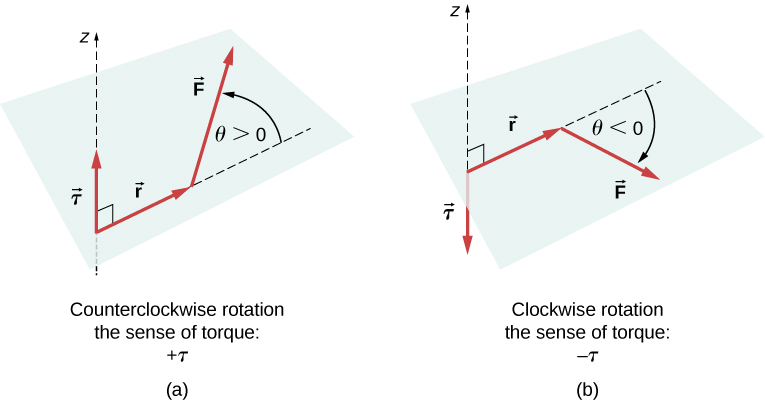
where is the length of the lever arm of the force and is the magnitude of the force (as you saw in Fixed-Axis Rotation). The angle is the angle between vectors and measuring from vector to vector in the counterclockwise direction (Figure 12.2). When using Equation 12.10, we often compute the magnitude of torque and assign its sense as either positive or negative depending on the direction of rotation caused by this torque alone. In Equation 12.9, net torque is the sum of terms, with each term computed from Equation 12.10, and each term must have the correct sense. Similarly, in Equation 12.7, we assign the sign to force components in the x-direction and the sign to components in the x-direction. The same rule must be consistently followed in Equation 12.8, when computing force components along the y-axis.
英語のヒント
OpenStax / Rice University, University Physics Volume 1, CC BY 4.0. Source-book artwork retained. · CC BY 4.0 · Source出典

Figure 12.2図 12.2
Torque of a force: (a) When the torque of a force causes counterclockwise rotation about the axis of rotation, we say that its sense is positive, which means the torque vector is parallel to the axis of rotation. (b) When torque of a force causes clockwise rotation about the axis, we say that its sense is negative, which means the torque vector is antiparallel to the axis of rotation.
英語のヒント
力のトルク。(a) 回転軸の周りに反時計回りの回転を生むトルクを正とする。トルクベクトルは回転軸と平行で同じ向きとなる。(b) 時計回りの回転を生むトルクを負とする。トルクベクトルは回転軸と反平行、すなわち逆向きとなる。
Additional Resources追加教材
In many equilibrium situations, one of the forces acting on the body is its weight. In free-body diagrams, the weight vector is attached to the center of gravity of the body. For all practical purposes, the center of gravity is identical to the center of mass, as you learned in Linear Momentum and Collisions on linear momentum and collisions. Only in situations where a body has a large spatial extension so that the gravitational field is nonuniform throughout its volume, are the center of gravity and the center of mass located at different points. In practical situations, however, even objects as large as buildings or cruise ships are located in a uniform gravitational field on Earth’s surface, where the acceleration due to gravity has a constant magnitude of In these situations, the center of gravity is identical to the center of mass. Therefore, throughout this chapter, we use the center of mass (CM) as the point where the weight vector is attached. Recall that the CM has a special physical meaning: When an external force is applied to a body at exactly its CM, the body as a whole undergoes translational motion and such a force does not cause rotation.
英語のヒント
多くのつり合いの状況で、物体に働く力の一つは重力である。力の図では、重力ベクトルを物体の重心に置く。「運動量と衝突」で学んだように、実用上、重心は質量中心と一致する。重心と質量中心が別の点になるのは、物体が空間的に大きく広がり、その内部で重力場が一様でなくなる場合だけである。実際には、建物やクルーズ船ほど大きな物体でも、地表の一様な重力場内にあり、重力加速度の大きさはである。この場合、重心と質量中心は一致する。したがって、この章では重力ベクトルの作用点として質量中心(CM)を用いる。CMには特別な物理的意味がある。物体のCMに正確に外力を加えると、物体全体は並進運動し、その力では回転が生じない。
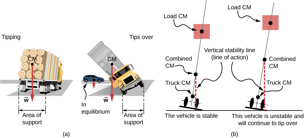
When the CM is located off the axis of rotation, a net gravitational torque occurs on an object. Gravitational torque is the torque caused by weight. This gravitational torque may rotate the object if there is no support present to balance it. The magnitude of the gravitational torque depends on how far away from the pivot the CM is located. For example, in the case of a tipping truck (Figure 12.3), the pivot is located on the line where the tires make contact with the road’s surface. If the CM is located high above the road’s surface, the gravitational torque may be large enough to turn the truck over. Passenger cars with a low-lying CM, close to the pavement, are more resistant to tipping over than are trucks.
英語のヒント
CMが回転軸から外れていると、物体には重力による合トルクが生じる。これを重力トルクという。つり合わせる支えがなければ、重力トルクは物体を回転させる。その大きさは、CMが支点からどれだけ離れているかに依存する。例えば、傾いたトラック(図12.3)の支点は、タイヤが路面に接する線上にある。CMが路面から高い位置にあると、重力トルクがトラックを横転させるほど大きくなることがある。CMが路面近くの低い位置にある乗用車は、トラックより横転しにくい。
OpenStax / Rice University, University Physics Volume 1, CC BY 4.0. Source-book artwork retained. · CC BY 4.0 · Source出典

Figure 12.3図 12.3
The distribution of mass affects the position of the center of mass (CM), where the weight vector is attached. If the center of gravity is within the area of support, the truck returns to its initial position after tipping [see the left panel in (b)]. But if the center of gravity lies outside the area of support, the truck turns over [see the right panel in (b)]. Both vehicles in (b) are out of equilibrium. Notice that the car in (a) is in equilibrium: The low location of its center of gravity makes it hard to tip over.
英語のヒント
質量の分布は、重力ベクトルの作用点である質量中心(CM)の位置に影響する。重心が支持範囲内にあれば、傾いたトラックは元の位置に戻る[(b)の左図]。重心が支持範囲外なら横転する[(b)の右図]。(b)の両車ともつり合いから外れている。(a)の乗用車はつり合っている。重心の位置が低いため、横転しにくい。
Additional Resources追加教材
Example 12.1例題 12.1
Center of Gravity of a Car自動車の重心
A passenger car with a 2.5-m wheelbase has 52% of its weight on the front wheels on level ground, as illustrated in Figure 12.4. Where is the CM of this car located with respect to the rear axle?
英語のヒント
図12.4のように、ホイールベース2.5 mの乗用車が水平な地面にあり、重さの52%を前輪が支えている。後車軸を基準にすると、この車のCMはどこにあるか。
Image omitted because its reuse rights could not be verified.権利の確認ができないため画像を割愛。
Figure 12.4図 12.4
The weight distribution between the axles of a car. Where is the center of gravity located? (credit "car": modification of work by Jane Whitney)
英語のヒント
前後の車軸にかかる車の重さの分配。重心はどこにあるか。(「車」:ジェーン・ホイットニーの作品を改変)
Strategy方針
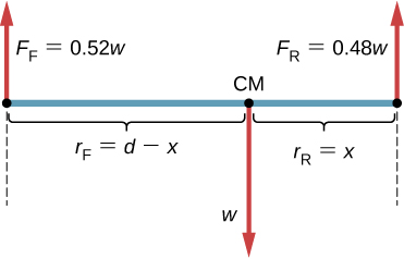
We do not know the weight w of the car. All we know is that when the car rests on a level surface, 0.52w pushes down on the surface at contact points of the front wheels and 0.48w pushes down on the surface at contact points of the rear wheels. Also, the contact points are separated from each other by the distance At these contact points, the car experiences normal reaction forces with magnitudes and on the front and rear axles, respectively. We also know that the car is an example of a rigid body in equilibrium whose entire weight w acts at its CM. The CM is located somewhere between the points where the normal reaction forces act, somewhere at a distance x from the point where acts. Our task is to find x. Thus, we identify three forces acting on the body (the car), and we can draw a free-body diagram for the extended rigid body, as shown in Figure 12.5.
英語のヒント
車の重さwは分からない。分かるのは、水平面で静止するとき、前輪の接点で0.52w、後輪の接点で0.48wの力が面を下向きに押すことである。接点どうしの距離はである。接点で車は、前車軸に大きさ、後車軸に大きさの垂直抗力を受ける。また、車はつり合いにある剛体で、重力wの全体がCMに働く。CMは二つの垂直抗力の作用点の間にあり、の作用点から距離xの位置にある。このxを求める。車に働く三つの力を特定できたので、図12.5のように、広がりを持つ剛体の力の図を描ける。
OpenStax / Rice University, University Physics Volume 1, CC BY 4.0. Source-book artwork retained. · CC BY 4.0 · Source出典

Figure 12.5図 12.5
The free-body diagram for the car clearly indicates force vectors acting on the car and distances to the center of mass (CM). When CM is selected as the pivot point, these distances are lever arms of normal reaction forces. Notice that vector magnitudes and lever arms do not need to be drawn to scale, but all quantities of relevance must be clearly labeled.
英語のヒント
車の力の図では、働く力のベクトルと質量中心(CM)までの距離を明示する。CMを支点に選ぶと、この距離が垂直抗力の腕の長さになる。ベクトルの大きさや腕の長さは縮尺どおりに描く必要はないが、関係するすべての量を明確に記す必要がある。
We are almost ready to write down equilibrium conditions Equation 12.7 through Equation 12.9 for the car, but first we must decide on the reference frame. Suppose we choose the x-axis along the length of the car, the y-axis vertical, and the z-axis perpendicular to this xy-plane. With this choice we only need to write Equation 12.7 and Equation 12.9 because all the y-components are identically zero. Now we need to decide on the location of the pivot point. We can choose any point as the location of the axis of rotation (z-axis). Suppose we place the axis of rotation at CM, as indicated in the free-body diagram for the car. At this point, we are ready to write the equilibrium conditions for the car.
英語のヒント
Solution解答
Each equilibrium condition contains only three terms because there are forces acting on the car. The first equilibrium condition, Equation 12.7, reads
英語のヒント
車に働く力は個なので、それぞれのつり合いの式は三つの項だけを含む。第1条件の式12.7は次のようになる。
(12.11)
This condition is trivially satisfied because when we substitute the data, Equation 12.11 becomes The second equilibrium condition, Equation 12.9, reads
英語のヒント
(12.12)
where is the torque of force is the gravitational torque of force w, and is the torque of force When the pivot is located at CM, the gravitational torque is identically zero because the lever arm of the weight with respect to an axis that passes through CM is zero. The lines of action of both normal reaction forces are perpendicular to their lever arms, so in Equation 12.10, we have for both forces. From the free-body diagram, we read that torque causes clockwise rotation about the pivot at CM, so its sense is negative; and torque causes counterclockwise rotation about the pivot at CM, so its sense is positive. With this information, we write the second equilibrium condition as
英語のヒント
ここで、は前輪の力によるトルク、は力によるトルクである。は、それぞれ前輪の力と、重力wによるトルクを表す。支点がCMにあると、CMを通る軸に関する重力の腕の長さがゼロなので、重力トルクはゼロである。二つの垂直抗力の作用線は、それぞれの腕に垂直なので、式12.10ではどちらもとなる。力の図より、はCMの周りに時計回りの回転を生むため負、は反時計回りの回転を生むため正である。これより、第2条件を次のように書ける。
(12.13)
With the help of the free-body diagram, we identify the force magnitudes and and their corresponding lever arms and We can now write the second equilibrium condition, Equation 12.13, explicitly in terms of the unknown distance x:
英語のヒント
力の図から、力の大きさと、対応する腕の長さとを特定できる。第2条件の式12.13を、未知の距離xを使って具体的に書くと、次のようになる。
(12.14)
Here the weight w cancels and we can solve the equation for the unknown position x of the CM. The answer is
英語のヒント
重さwは約分でき、CMの未知の位置xについて解ける。答えはである。
Solution解答
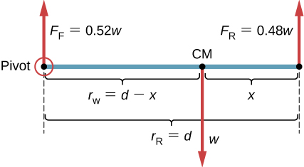
Choosing the pivot at the position of the front axle does not change the result. The free-body diagram for this pivot location is presented in Figure 12.6. For this choice of pivot point, the second equilibrium condition is
英語のヒント
支点を前車軸に選んでも、結果は変わらない。この場合の力の図を図12.6に示す。第2条件は次のようになる。
(12.15)
When we substitute the quantities indicated in the diagram, we obtain
英語のヒント
図に示した量を代入すると、次式を得る。
(12.16)
OpenStax / Rice University, University Physics Volume 1, CC BY 4.0. Source-book artwork retained. · CC BY 4.0 · Source出典

Figure 12.6図 12.6
The equivalent free-body diagram for the car; the pivot is clearly indicated.
英語のヒント
支点を明示した、同じ車の別の力の図。
Significance考察
This example shows that when solving static equilibrium problems, we are free to choose the pivot location. For different choices of the pivot point we have different sets of equilibrium conditions to solve. However, all choices lead to the same solution to the problem.
英語のヒント
この例題が示すように、静的つり合いの問題では、支点の位置を自由に選べる。支点の選び方によって解くつり合いの式は変わるが、どれを選んでも同じ答えになる。