プリンキピア

第12章静的つり合いと弾性

In the next example, we show how to use the first equilibrium condition (equation for forces) in the vector form given by Equation 12.7 and Equation 12.8. We present this solution to illustrate the importance of a suitable choice of reference frame. Although all inertial reference frames are equivalent and numerical solutions obtained in one frame are the same as in any other, an unsuitable choice of reference frame can make the solution quite lengthy and convoluted, whereas a wise choice of reference frame makes the solution straightforward. We show this in the equivalent solution to the same problem. This particular example illustrates an application of static equilibrium to biomechanics.
英語のヒント
次の例題では、第1条件、すなわち力のつり合いを、式12.7と式12.8のベクトルの形で使う。適切な基準系を選ぶことの重要性を示す例である。すべての慣性基準系は等価で、どの基準系でも数値の答えは同じになる。しかし、選び方が不適切だと解法が長く複雑になり、適切に選べば簡単になる。同じ問題を別の基準系で解いて、このことを示す。この例題は、生体力学への静的つり合いの応用でもある。
Example 12.4例題 12.4

Forces in the Forearm前腕に働く力

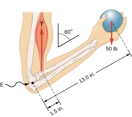
A weightlifter is holding a 50.0-lb weight (equivalent to 222.4 N) with his forearm, as shown in Figure 12.11. His forearm is positioned at β=60° with respect to his upper arm. The forearm is supported by a contraction of the biceps muscle, which causes a torque around the elbow. Assuming that the tension in the biceps acts along the vertical direction given by gravity, what tension must the muscle exert to hold the forearm at the position shown? What is the force on the elbow joint? Assume that the forearm’s weight is negligible. Give your final answers in SI units.
英語のヒント
重量挙げの選手が、図12.11のように、前腕で50.0 lb(222.4 Nに相当)のおもりを支えている。前腕は上腕となす角β=60°の位置にある。上腕二頭筋が収縮し、肘の周りにトルクを生むことで前腕を支える。二頭筋の張力が重力で定まる鉛直方向に沿って働くとすると、図の姿勢を保つために筋肉が生む張力はいくらか。肘関節に働く力はいくらか。前腕自体の重さは無視できるとし、最終的な答えをSI単位で示せ。
肘の周りに回した前腕の模式図。手のひらで50 lbの球を持つ。肘から球まで13 in、肘から二頭筋の作用点まで1.5 inである。前腕は上腕と60度をなす。

OpenStax / Rice University, University Physics Volume 1, CC BY 4.0. Source-book artwork retained. · CC BY 4.0 · Source出典

Figure 12.11図 12.11
The forearm is rotated around the elbow (E) by a contraction of the biceps muscle, which causes tension T→M.
英語のヒント
上腕二頭筋の収縮が張力T→Mを生み、前腕を肘Eの周りに回転させる。

Strategy方針

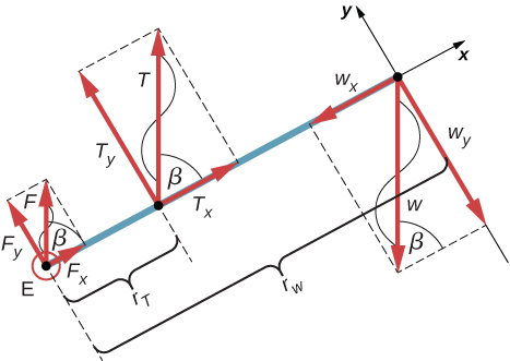
We identify three forces acting on the forearm: the unknown force F→ at the elbow; the unknown tension T→M in the muscle; and the weight w→ with magnitude w=50lb. We adopt the frame of reference with the x-axis along the forearm and the pivot at the elbow. The vertical direction is the direction of the weight, which is the same as the direction of the upper arm. The x-axis makes an angle β=60° with the vertical. The y-axis is perpendicular to the x-axis. Now we set up the free-body diagram for the forearm. First, we draw the axes, the pivot, and the three vectors representing the three identified forces. Then we locate the angle β and represent each force by its x- and y-components, remembering to cross out the original force vector to avoid double counting. Finally, we label the forces and their lever arms. The free-body diagram for the forearm is shown in Figure 12.12. At this point, we are ready to set up equilibrium conditions for the forearm. Each force has x- and y-components; therefore, we have two equations for the first equilibrium condition, one equation for each component of the net force acting on the forearm.
英語のヒント
前腕に働く三つの力は、肘での未知の力F→、筋肉の未知の張力T→M、大きさw=50lbのおもりの重力w→である。x軸を前腕に沿わせ、肘を支点にする。鉛直方向は重力の向きであり、上腕の方向と一致する。x軸は鉛直となす角β=60°を持ち、y軸はx軸に垂直である。力の図には、軸、支点、三つの力のベクトルを描く。次に角βを定め、各力をx成分とy成分で表す。二重に数えないよう、元の力のベクトルは消す。最後に力と腕の長さの記号を記す。図12.12がその力の図である。これでつり合いの条件を立てられる。各力がx成分とy成分を持つので、第1条件には、合力の各成分に対応する二つの式がある。
前腕の力の図。Eに力F、Eからr_Tの位置に力T、反対端のEからr_wの位置に重力Wが働く。各力のx、y成分を示す。FとTはx軸と角βをなし、Wは自身とy軸への射影点を結ぶ線と角βをなす。

OpenStax / Rice University, University Physics Volume 1, CC BY 4.0. Source-book artwork retained. · CC BY 4.0 · Source出典

Figure 12.12図 12.12
Free-body diagram for the forearm: The pivot is located at point E (elbow).
英語のヒント
前腕の力の図。支点は肘のE点にある。
Notice that in our frame of reference, contributions to the second equilibrium condition (for torques) come only from the y-components of the forces because the x-components of the forces are all parallel to their lever arms, so that for any of them we have sinθ=0 in Equation 12.10. For the y-components we have θ=±90° in Equation 12.10. Also notice that the torque of the force at the elbow is zero because this force is attached at the pivot. So the contribution to the net torque comes only from the torques of Ty and of wy.
英語のヒント
この基準系では、トルクのつり合いである第2条件に寄与するのは、力のy成分だけである。x成分はすべて腕と平行なので、式12.10でsinθ=0となる。y成分については、式12.10でθ=±90°となる。肘での力は支点に働くので、トルクはゼロである。したがって、合トルクに寄与するのはTyとwyによるトルクだけである。

Solution解答

We see from the free-body diagram that the x-component of the net force satisfies the equation
英語のヒント
力の図より、合力のx成分は次の式を満たす。
+Fx+Tx−wx=0
(12.21)
and the y-component of the net force satisfies
英語のヒント
合力のy成分は、次式を満たす。
+Fy+Ty−wy=0.
(12.22)
Equation 12.21 and Equation 12.22 are two equations of the first equilibrium condition (for forces). Next, we read from the free-body diagram that the net torque along the axis of rotation is
英語のヒント
式12.21と式12.22が、力に関する第1条件の二つの式である。次に力の図から、回転軸方向の合トルクは次のようになる。
+rTTy−rwwy=0.
(12.23)
Equation 12.23 is the second equilibrium condition (for torques) for the forearm. The free-body diagram shows that the lever arms are rT=1.5in. and rw=13.0in. At this point, we do not need to convert inches into SI units, because as long as these units are consistent in Equation 12.23, they cancel out. Using the free-body diagram again, we find the magnitudes of the component forces:
英語のヒント
式12.23は、前腕についての第2条件、トルクのつり合いの式である。図より、腕の長さはrT=1.5inとrw=13.0inである。この段階ではインチをSI単位へ換算する必要はない。式12.23で単位がそろっていれば、約分で消えるからである。再び力の図を使い、各成分の大きさを求める。
Fx=Fcosβ=Fcos60°=F/2Tx=Tcosβ=Tcos60°=T/2wx=wcosβ=wcos60°=w/2Fy=Fsinβ=Fsin60°=F3/2Ty=Tsinβ=Tsin60°=T3/2wy=wsinβ=wsin60°=w3/2.
We substitute these magnitudes into Equation 12.21, Equation 12.22, and Equation 12.23 to obtain, respectively,
英語のヒント
これらの大きさを式12.21、式12.22、式12.23へ代入すると、それぞれ次式を得る。
F/2+T/2−w/2=0F3/2+T3/2−w3/2=0rTT3/2−rww3/2=0.
When we simplify these equations, we see that we are left with only two independent equations for the two unknown force magnitudes, F and T, because Equation 12.21 for the x-component is equivalent to Equation 12.22 for the y-component. In this way, we obtain the first equilibrium condition for forces
英語のヒント
これらの式を整理すると、未知の力の大きさFとTに対し、独立な式は二つだけ残る。x成分の式12.21は、y成分の式12.22と同値だからである。よって、力に関する第1条件は次式となる。
F+T−w=0
(12.24)
and the second equilibrium condition for torques
英語のヒント
トルクに関する第2条件は、次式となる。
rTT−rww=0.
(12.25)
The magnitude of tension in the muscle is obtained by solving Equation 12.25:
英語のヒント
式12.25を解くと、筋肉の張力の大きさが求まる。
T=rwrTw=13.01.5(50 lb)=43313lb≃433.3lb.
The force at the elbow is obtained by solving Equation 12.24:
英語のヒント
式12.24を解くと、肘に働く力が求まる。
F=w−T=50.0lb−433.3lb=−383.3lb.
The negative sign in the equation tells us that the actual force at the elbow is antiparallel to the working direction adopted for drawing the free-body diagram. In the final answer, we convert the forces into SI units of force. The answer is
英語のヒント
式の負の符号は、肘での実際の力が、力の図で仮定した向きと反平行であることを示す。最後に力をSI単位へ換算すると、答えは次のようになる。
F=383.3lb=383.3(4.448N)=1705N downwardT=433.3lb=433.3(4.448N)=1927N upward.
F=383.3lb=383.3(4.448N)=1705N 下向きT=433.3lb=433.3(4.448N)=1927N 上向き

Significance考察

Two important issues here are worth noting. The first concerns conversion into SI units, which can be done at the very end of the solution as long as we keep consistency in units. The second important issue concerns the hinge joints such as the elbow. In the initial analysis of a problem, hinge joints should always be assumed to exert a force in an arbitrary direction, and then you must solve for all components of a hinge force independently. In this example, the elbow force happens to be vertical because the problem assumes the tension by the biceps to be vertical as well. Such a simplification, however, is not a general rule.
英語のヒント
ここでは二つの点に注意が必要である。一つはSI単位への換算で、単位を一貫してそろえていれば、最後に換算してよい。もう一つは肘のような蝶番関節である。問題の初期の解析では、関節は任意の向きに力を及ぼすと仮定し、その力の全成分を独立に求めなければならない。この例で肘の力が鉛直になるのは、二頭筋の張力も鉛直と仮定したためである。この簡略化が一般に成り立つわけではない。

Solution解答

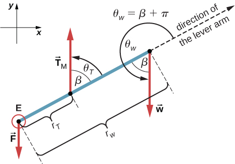
Suppose we adopt a reference frame with the direction of the y-axis along the 50-lb weight and the pivot placed at the elbow. In this frame, all three forces have only y-components, so we have only one equation for the first equilibrium condition (for forces). We draw the free-body diagram for the forearm as shown in Figure 12.13, indicating the pivot, the acting forces and their lever arms with respect to the pivot, and the angles θT and θw that the forces T→M and w→ (respectively) make with their lever arms. In the definition of torque given by Equation 12.10, the angle θT is the direction angle of the vector T→M, counted counterclockwise from the radial direction of the lever arm that always points away from the pivot. By the same convention, the angle θw is measured counterclockwise from the radial direction of the lever arm to the vector w→. Done this way, the non-zero torques are most easily computed by directly substituting into Equation 12.10 as follows:
英語のヒント
今度は、y軸を50 lbのおもりの重力の向きに取り、肘を支点とする基準系を選ぼう。この基準系では、三つの力はすべてy成分だけを持つため、第1条件の式は一つだけとなる。図12.13のように、力の図へ支点、力、腕の長さを記し、力T→M、w→がそれぞれの腕となす角θT、θwも示す。トルクの定義である式12.10では、θTは、支点から外へ向かう腕の方向から、ベクトルT→Mへ反時計回りに測る角である。同じ規約で、θwは腕の方向からw→へ反時計回りに測る。この方法なら、式12.10へ直接代入し、ゼロでないトルクを簡単に計算できる。
τT=rTTsinθT=rTTsinβ=rTTsin60°=+rTT3/2τw=rwwsinθw=rwwsin(β+180°)=−rwwsinβ=−rww3/2.
前腕の力の図。Eに力F、Eからr_Tの位置に力T_M、反対端のEからr_wの位置に重力Wが働き、x、y成分も示される。T_Mと腕の方向のなす角θ_Tはβ、Wと腕の方向のなす角θ_wはβ+πである。

OpenStax / Rice University, University Physics Volume 1, CC BY 4.0. Source-book artwork retained. · CC BY 4.0 · Source出典

Figure 12.13図 12.13
Free-body diagram for the forearm for the equivalent solution. The pivot is located at point E (elbow).
英語のヒント
別解で用いる前腕の力の図。支点は肘のE点にある。
The second equilibrium condition, τT+τw=0, can be now written as
英語のヒント
第2条件τT+τw=0は、次のように書ける。
rTT3/2−rww3/2=0.
(12.26)
From the free-body diagram, the first equilibrium condition (for forces) is
英語のヒント
力の図から、力に関する第1条件は次のようになる。
−F+T−w=0.
(12.27)
Equation 12.26 is identical to Equation 12.25 and gives the result T=433.3lb. Equation 12.27 gives
英語のヒント
式12.26は式12.25と同じであり、T=433.3lbを与える。式12.27からは次の値を得る。
F=T−w=433.3lb−50.0lb=383.3lb.
We see that these answers are identical to our previous answers, but the second choice for the frame of reference leads to an equivalent solution that is simpler and quicker because it does not require that the forces be resolved into their rectangular components.
英語のヒント
答えは先ほどと一致するが、二つ目の基準系を選ぶと、力を直交成分へ分解する必要がないため、同じ問題をより簡単に、短時間で解ける。
Example 12.5例題 12.5

A Ladder Resting Against a Wall壁に立て掛けたはしご

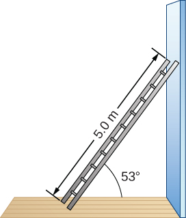
A uniform ladder is L=5.0m long and weighs 400.0 N. The ladder rests against a slippery vertical wall, as shown in Figure 12.14. The minimum inclination angle between the ladder and the rough floor below which the ladder slips is β=53°. Find the reaction forces from the floor and from the wall on the ladder and the coefficient of static friction μs at the interface of the ladder with the floor that prevents the ladder from slipping.
英語のヒント
長さL=5.0m、重さ400.0 Nの一様なはしごを、図12.14のように、滑らかな鉛直の壁に立て掛ける。はしごと粗い床のなす角がβ=53°より小さくなると、はしごは滑る。床と壁がはしごに及ぼす力と、床との接触面で滑りを防ぐ静止摩擦係数μsを求めよ。
長さ5.0 mのはしごを壁に立て掛けた模式図。床となす角は53度である。

OpenStax / Rice University, University Physics Volume 1, CC BY 4.0. Source-book artwork retained. · CC BY 4.0 · Source出典

Figure 12.14図 12.14
A 5.0-m-long ladder rests against a frictionless wall.
英語のヒント
長さ5.0 mのはしごを、摩擦のない壁に立て掛ける。

Strategy方針

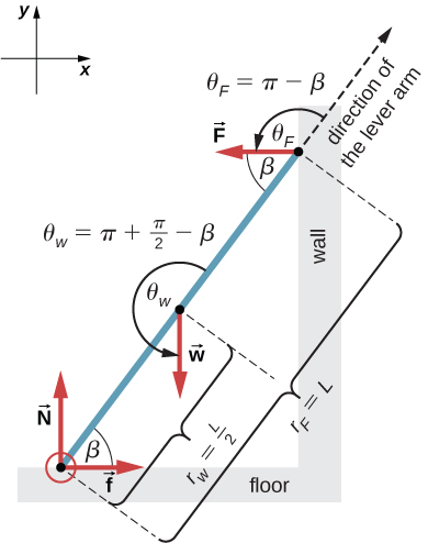
We can identify four forces acting on the ladder. The first force is the normal reaction force N from the floor in the upward vertical direction. The second force is the static friction force f=μsN directed horizontally along the floor toward the wall—this force prevents the ladder from slipping. These two forces act on the ladder at its contact point with the floor. The third force is the weight w of the ladder, attached at its CM located midway between its ends. The fourth force is the normal reaction force F from the wall in the horizontal direction away from the wall, attached at the contact point with the wall. There are no other forces because the wall is slippery, which means there is no friction between the wall and the ladder. Based on this analysis, we adopt the frame of reference with the y-axis in the vertical direction (parallel to the wall) and the x-axis in the horizontal direction (parallel to the floor). In this frame, each force has either a horizontal component or a vertical component but not both, which simplifies the solution. We select the pivot at the contact point with the floor. In the free-body diagram for the ladder, we indicate the pivot, all four forces and their lever arms, and the angles between lever arms and the forces, as shown in Figure 12.15. With our choice of the pivot location, there is no torque either from the normal reaction force N or from the static friction f because they both act at the pivot.
英語のヒント
はしごには四つの力が働く。第一は床から鉛直上向きの垂直抗力N、第二は床に沿って壁へ向かう静止摩擦力f=μsNで、これが滑りを防ぐ。二つとも、はしごと床の接点に働く。第三は、はしごの両端の中間にあるCMに働く重力wである。第四は壁から水平方向に離れる向きの垂直抗力Fで、壁との接点に働く。壁は滑らかで摩擦がないので、他の力はない。y軸を壁に平行な鉛直方向、x軸を床に平行な水平方向に取る。この基準系では、各力は水平成分か鉛直成分の一方だけを持ち、解法が簡単になる。支点は床との接点に選ぶ。図12.15のように、力の図へ支点、四つの力と腕の長さ、腕と力のなす角を記す。垂直抗力Nと静止摩擦力fは支点に働くため、この支点の周りにはトルクを生まない。
床と角βをなし、壁に接するはしごの力の図。床との接点に、床に垂直なNが働く。はしごの中点にW、壁との接点に壁に垂直なFが働く。Wと腕の方向のなす角θ_wはπ+π/2−β、Fと腕の方向のなす角θ_Fはπ−βである。

OpenStax / Rice University, University Physics Volume 1, CC BY 4.0. Source-book artwork retained. · CC BY 4.0 · Source出典

Figure 12.15図 12.15
Free-body diagram for a ladder resting against a frictionless wall.
英語のヒント
摩擦のない壁に立て掛けたはしごの力の図。

Solution解答

From the free-body diagram, the net force in the x-direction is
英語のヒント
力の図より、x方向の合力は次のようになる。
+f−F=0
(12.28)
the net force in the y-direction is
英語のヒント
y方向の合力は、次のようになる。
+N−w=0
(12.29)
and the net torque along the rotation axis at the pivot point is
英語のヒント
支点を通る回転軸に沿う合トルクは、次のようになる。
τw+τF=0.
(12.30)
where τw is the torque of the weight w and τF is the torque of the reaction F. From the free-body diagram, we identify that the lever arm of the reaction at the wall is rF=L=5.0m and the lever arm of the weight is rw=L/2=2.5m. With the help of the free-body diagram, we identify the angles to be used in Equation 12.10 for torques: θF=180°−β for the torque from the reaction force with the wall, and θw=180°+(90°−β) for the torque due to the weight. Now we are ready to use Equation 12.10 to compute torques:
英語のヒント
ここで、τwは重力wのトルク、τFは抗力Fのトルクである。図から、壁の抗力の腕はrF=L=5.0m、重力の腕はrw=L/2=2.5mと分かる。式12.10で使う角は、壁の抗力についてθF=180°−β、重力についてθw=180°+(90°−β)である。これを式12.10へ入れ、トルクを計算する。
τw=rwwsinθw=rwwsin(180°+90°−β)=−L2wsin(90°−β)=−L2wcosβτF=rFFsinθF=rFFsin(180°−β)=LFsinβ.
We substitute the torques into Equation 12.30 and solve for F:
英語のヒント
トルクを式12.30へ代入し、F:について解く。
−L2wcosβ+LFsinβ=0F=w2cotβ=400.0N2cot53°=150.7N
(12.31)
We obtain the normal reaction force with the floor by solving Equation 12.29: N=w=400.0N. The magnitude of friction is obtained by solving Equation 12.28: f=F=150.7N. Since the ladder will slip if the angle is any smaller, the static friction force is at its maximum angle and the coefficient of static friction is μs=f/N=150.7/400.0=0.377.
英語のヒント
式12.29を解くと、床からの垂直抗力はN=w=400.0Nとなる。式12.28を解くと、摩擦力の大きさはf=F=150.7Nとなる。これより角度が少しでも小さくなるとはしごが滑るため、この角度では静止摩擦力が限界に達しており、静止摩擦係数はμs=f/N=150.7/400.0=0.377である。
The net force on the ladder at the contact point with the floor is the vector sum of the normal reaction from the floor and the static friction forces:
英語のヒント
床との接点ではしごに働く合力は、床からの垂直抗力と静止摩擦力のベクトル和である。
F→floor=f→+N→=(150.7 N)(−i^)+(400.0N)(+j^)=(−150.7i^+400.0j^)N.
F→床=f→+N→=(150.7 N)(−i^)+(400.0N)(+j^)=(−150.7i^+400.0j^)N
Its magnitude is
英語のヒント
その大きさは、
Ffloor=f2+N2=150.72+400.02N=427.4N
F床=f2+N2=150.72+400.02N=427.4N
and its direction is
英語のヒント
向きは、次のようになる。
φ=tan−1(N/f)=tan−1(400.0/150.7)=69.3°above the floor.
φ=tan−1(N/f)=tan−1(400.0/150.7)=69.3°(床より上)
We should emphasize here two general observations of practical use. First, notice that when we choose a pivot point, there is no expectation that the system will actually pivot around the chosen point. The ladder in this example is not rotating at all but firmly stands on the floor; nonetheless, its contact point with the floor is a good choice for the pivot. Second, notice when we use Equation 12.10 for the computation of individual torques, we do not need to resolve the forces into their normal and parallel components with respect to the direction of the lever arm, and we do not need to consider a sense of the torque. As long as the angle in Equation 12.10 is correctly identified—with the help of a free-body diagram—as the angle measured counterclockwise from the direction of the lever arm to the direction of the force vector, Equation 12.10 gives both the magnitude and the sense of the torque. This is because torque is the vector product of the lever-arm vector crossed with the force vector, and Equation 12.10 expresses the rectangular component of this vector product along the axis of rotation.
英語のヒント
実際の計算で役立つ二つの一般的な点を強調しておこう。第一に、支点を選んだからといって、系が実際にその点の周りを回る必要はない。この例のはしごはまったく回転せず、床の上にしっかり立つ。それでも、床との接点を支点に選ぶと便利である。第二に、式12.10で各トルクを計算するとき、力を腕に垂直・平行な成分に分けたり、トルクの向きを別に判定したりする必要はない。力の図を使い、式12.10の角度を腕の方向から力の方向へ反時計回りに正しく測れば、式12.10だけで大きさと向きの両方が得られる。トルクは腕のベクトルと力のベクトルの外積であり、式12.10はその回転軸方向の直交成分を表すからである。

Significance考察

This result is independent of the length of the ladder because L is cancelled in the second equilibrium condition, Equation 12.31. No matter how long or short the ladder is, as long as its weight is 400 N and the angle with the floor is 53°, our results hold. But the ladder will slip if the net torque becomes negative in Equation 12.31. This happens for some angles when the coefficient of static friction is not great enough to prevent the ladder from slipping.
英語のヒント
第2条件の式12.31ではLが約分で消えるため、結果ははしごの長さに依存しない。長くても短くても、重さが400 Nで床との角が53°なら、結果は同じである。しかし、式12.31の合トルクが負になるとはしごは滑る。静止摩擦係数が滑りを防ぐのに十分大きくない角度で、これが起きる。
Example 12.6例題 12.6

Forces on Door Hingesドアのちょうつがいに働く力

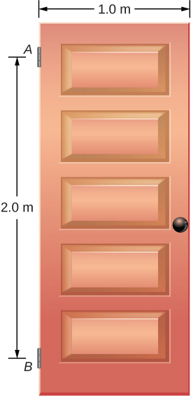
A swinging door that weighs w=400.0N is supported by hinges A and B so that the door can swing about a vertical axis passing through the hinges Figure 12.16. The door has a width of b=1.00m, and the door slab has a uniform mass density. The hinges are placed symmetrically at the door’s edge in such a way that the door’s weight is evenly distributed between them. The hinges are separated by distance a=2.00m. Find the forces on the hinges when the door rests half-open.
英語のヒント
重さw=400.0Nの開き戸が、ちょうつがいA、Bを通る鉛直軸の周りに開閉できるように支えられている(図12.16)。ドアの幅はb=1.00mで、板の質量密度は一様である。ちょうつがいは端に対称に取り付けられ、重さを均等に分担する。両者の距離はa=2.00mである。ドアが半開きで静止しているとき、ちょうつがいに働く力を求めよ。
鉛直な開き戸を、A、Bの2か所のちょうつがいで支えた模式図。AとBの間隔は2 m、ドアの幅は1 mである。

OpenStax / Rice University, University Physics Volume 1, CC BY 4.0. Source-book artwork retained. · CC BY 4.0 · Source出典

Figure 12.16図 12.16
A 400-N swinging vertical door is supported by two hinges attached at points A and B.
英語のヒント
重さ400 Nの鉛直な開き戸を、AとBのちょうつがいで支える。

Strategy方針

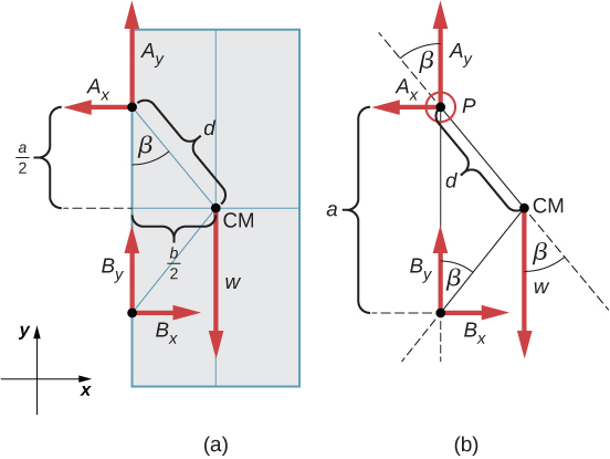
The forces that the door exerts on its hinges can be found by simply reversing the directions of the forces that the hinges exert on the door. Hence, our task is to find the forces from the hinges on the door. Three forces act on the door slab: an unknown force A→ from hinge A, an unknown force B→ from hinge B, and the known weight w→ attached at the center of mass of the door slab. The CM is located at the geometrical center of the door because the slab has a uniform mass density. We adopt a rectangular frame of reference with the y-axis along the direction of gravity and the x-axis in the plane of the slab, as shown in panel (a) of Figure 12.17, and resolve all forces into their rectangular components. In this way, we have four unknown component forces: two components of force A→ (Ax and Ay), and two components of force B→ (Bx and By). In the free-body diagram, we represent the two forces at the hinges by their vector components, whose assumed orientations are arbitrary. Because there are four unknowns (Ax, Bx, Ay, and By), we must set up four independent equations. One equation is the equilibrium condition for forces in the x-direction. The second equation is the equilibrium condition for forces in the y-direction. The third equation is the equilibrium condition for torques in rotation about a hinge. Because the weight is evenly distributed between the hinges, we have the fourth equation, Ay=By. To set up the equilibrium conditions, we draw a free-body diagram and choose the pivot point at the upper hinge, as shown in panel (b) of Figure 12.17. Finally, we solve the equations for the unknown force components and find the forces.
英語のヒント
ドアがちょうつがいに及ぼす力は、ちょうつがいがドアに及ぼす力の向きを逆にすれば求まる。そこで、ドアが受ける力を求める。ドアには三つの力が働く。ちょうつがいAからの未知の力A→、ちょうつがいBからの未知の力B→、ドアのCMに働く既知の重力w→である。板の密度が一様なので、CMは幾何学的な中心にある。図12.17(a)のように、y軸を重力の方向、x軸を板の面内に取り、各力を直交成分へ分ける。未知量は、A→の成分(Ax、Ay)と、B→の成分(Bx、By)の四つとなる。図では、ちょうつがいの力を任意に仮定した向きの成分で表す。未知量(Ax、Bx、Ay、By)が四つなので、独立な式が四つ必要である。一つ目はx方向の力、二つ目はy方向の力、三つ目はちょうつがいの周りのトルクのつり合いである。重さを均等に分担するので、四つ目の式はAy=Byとなる。図12.17(b)のように、上側のちょうつがいを支点として力の図を描く。これらの式を解いて未知の成分を求め、力を決定する。
(a) A、Bのちょうつがいで支えたドアの幾何学的配置。A、Bに力A、Bが働き、そのx、y成分を示す。CMにwが働く。CMはAから下へa/2、右へb/2にあり、AとCMを結ぶ線は壁の端と角βをなす。(b) 力の図では、A_yはPとCMを結ぶ線と角β、B_yはBとCMを結ぶ線と角βをなす。WはPとCMを結ぶ線の延長と角βをなす。PとCMの距離はdである。

OpenStax / Rice University, University Physics Volume 1, CC BY 4.0. Source-book artwork retained. · CC BY 4.0 · Source出典

Figure 12.17図 12.17
(a) Geometry and (b) free-body diagram for the door.
英語のヒント
ドアの(a)幾何学的配置と、(b)力の図。

Solution解答

From the free-body diagram for the door we have the first equilibrium condition for forces:
英語のヒント
ドアの力の図から、第1条件である力のつり合いは、次のようになる。
inx-direction:−Ax+Bx=0⇒Ax=Bx iny-direction:+Ay+By−w=0⇒Ay=By=w2=400.0N2=200.0N.
x方向:−Ax+Bx=0⇒Ax=Bx y方向:+Ay+By−w=0⇒Ay=By=w2=400.0N2=200.0N.
We select the pivot at point P (upper hinge, per the free-body diagram) and write the second equilibrium condition for torques in rotation about point P:
英語のヒント
力の図の上側のちょうつがい、P点を支点に選ぶ。P点の周りのトルクについて、第2条件を書く。
pivot atP:τw+τBx+τBy=0.
支点:P:τw+τBx+τBy=0
(12.32)
We use the free-body diagram to find all the terms in this equation:
英語のヒント
力の図を使い、この式のすべての項を求める。
τw=dwsin(−β)=−dwsinβ=−dwb/2d=−wb2τBx=aBxsin90°=+aBxτBy=aBysin180°=0.
In evaluating sinβ, we use the geometry of the triangle shown in part (a) of the figure. Now we substitute these torques into Equation 12.32 and compute Bx:
英語のヒント
sinβを求めるには、図(a)の三角形の幾何学的関係を使う。これらのトルクを式12.32へ代入して、Bx:を計算する。
pivot atP:−wb2+aBx=0⇒Bx=wb2a=(400.0N)12·2=100.0N.
支点:P:−wb2+aBx=0⇒Bx=wb2a=(400.0N)12·2=100.0N
Therefore the magnitudes of the horizontal component forces are Ax=Bx=100.0N. The forces on the door are
英語のヒント
したがって、水平成分の大きさはAx=Bx=100.0Nである。ドアに働く力は次のとおりとなる。
at the upper hinge:F→Aon door=−100.0Ni^+200.0Nj^at the lower hinge:F→Bon door=+100.0Ni^+200.0Nj^.
上側のちょうつがい:F→A→ドア=−100.0Ni^+200.0Nj^下側のちょうつがい:F→B→ドア=+100.0Ni^+200.0Nj^.
The forces on the hinges are found from Newton’s third law as
英語のヒント
ニュートンの第3法則より、ちょうつがいに働く力は次のように求まる。
on the upper hinge:F→door onA=100.0Ni^−200.0Nj^on the lower hinge:F→door onB=−100.0Ni^−200.0Nj^.
上側のちょうつがいに働く力:F→ドア→A=100.0Ni^−200.0Nj^下側のちょうつがいに働く力:F→ドア→B=−100.0Ni^−200.0Nj^.

Significance考察

Note that if the problem were formulated without the assumption of the weight being equally distributed between the two hinges, we wouldn’t be able to solve it because the number of the unknowns would be greater than the number of equations expressing equilibrium conditions.
英語のヒント
重さが二つのちょうつがいに均等に分配されるという仮定がなければ、未知量の数がつり合いの式の数を超えるため、この問題は解けない。