プリンキピア

第2章ベクトル

Algebra of Vectors in Two Dimensions2次元でのベクトル代数

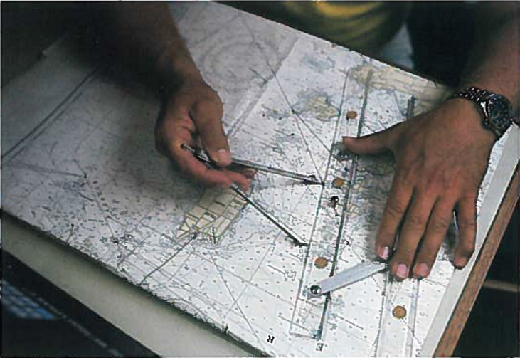
When vectors lie in a plane—that is, when they are in two dimensions—they can be multiplied by scalars, added to other vectors, or subtracted from other vectors in accordance with the general laws expressed by Equation 2.1, Equation 2.2, Equation 2.7, and Equation 2.8. However, the addition rule for two vectors in a plane becomes more complicated than the rule for vector addition in one dimension. We have to use the laws of geometry to construct resultant vectors, followed by trigonometry to find vector magnitudes and directions. This geometric approach is commonly used in navigation (Figure 2.9). In this section, we need to have at hand two rulers, a triangle, a protractor, a pencil, and an eraser for drawing vectors to scale by geometric constructions.
英語のヒント
ベクトルが平面内、すなわち2次元にある場合も、式2.1、式2.2、式2.7、式2.8で表される一般的な法則に従い、スカラーを掛けたり、ほかのベクトルを加えたり引いたりできる。ただし、平面内の二つのベクトルを加える規則は、1次元での加算より複雑になる。幾何学の法則で合ベクトルを作図し、続いて三角法を使って大きさと方向を求める必要がある。この幾何学的方法は、航法で広く用いられる(図2.9)。本節では、幾何学的な作図によって縮尺に従ってベクトルを描くために、定規2本、三角定規、分度器、鉛筆、消しゴムを手元に用意する。
ディバイダーと定規を使い、地図上の距離を測る人の写真。

OpenStax / Rice University, University Physics Volume 1, CC BY 4.0. Source-book artwork retained. · CC BY 4.0 · Source出典

Figure 2.9図 2.9
In navigation, the laws of geometry are used to draw resultant displacements on nautical maps.
英語のヒント
航法では、幾何学の法則を使って海図上に合成変位を描く。
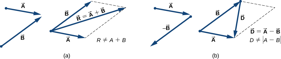
For a geometric construction of the sum of two vectors in a plane, we follow the parallelogram rule. Suppose two vectors A→ and B→ are at the arbitrary positions shown in Figure 2.10. Translate either one of them in parallel to the beginning of the other vector, so that after the translation, both vectors have their origins at the same point. Now, at the end of vector A→ we draw a line parallel to vector B→ and at the end of vector B→ we draw a line parallel to vector A→ (the dashed lines in Figure 2.10). In this way, we obtain a parallelogram. From the origin of the two vectors we draw a diagonal that is the resultant R→ of the two vectors: R→=A→+B→ (Figure 2.10(a)). The other diagonal of this parallelogram is the vector difference of the two vectors D→=A→−B→, as shown in Figure 2.10(b). Notice that the end of the difference vector is placed at the end of vector A→.
英語のヒント
平面内の二つのベクトルの和を作図するには、平行四辺形の法則に従う。二つのベクトルA→とB→が、図2.10の任意の位置にあるとしよう。一方を他方の始点へ平行移動し、両ベクトルの起点を同じ点にそろえる。次に、ベクトルA→の終点を通りB→に平行な直線と、ベクトルB→の終点を通りA→に平行な直線を引く(図2.10の破線)。こうすると、平行四辺形が得られる。二つのベクトルの共通の起点から対角線を引くと、それが両ベクトルの合ベクトルR→、すなわちR→=A→+B→である(図2.10(a))。この平行四辺形のもう一方の対角線は、図2.10(b)のように、両ベクトルの差D→=A→−B→である。差のベクトルの終点は、ベクトルA→の終点に置かれることに注意しよう。
ベクトルを加える平行四辺形の方法。(a)Aは右下、Bは右上を向く。両者の尾を合わせて実線の矢印で描き、Bの頭からAに平行な破線、Aの頭からBに平行な破線を引く。AとBと2本の破線が平行四辺形を作る。R = A + Bは、AとBの尾から破線どうしの交点へ、対角線に沿って伸びる。Rの大きさは、AとBの大きさの和には等しくない。(b)Aと−Bを示す。−Bは(a)のBを180度回したもので、Aは右下、−Bは左下を向く。続いてAとBを、元の方向のまま尾を合わせて実線で描く。Bの頭からAに平行な破線、Aの頭からBに平行な破線を引き、平行四辺形を作る。ベクトルDは、Bの頭からAの頭へ、対角線に沿って伸びる。D = A − Bだが、Dの大きさはAとBの大きさの差には等しくない。

OpenStax / Rice University, University Physics Volume 1, CC BY 4.0. Source-book artwork retained. · CC BY 4.0 · Source出典

Figure 2.10図 2.10
The parallelogram rule for the addition of two vectors. Make the parallel translation of each vector to a point where their origins (marked by the dot) coincide and construct a parallelogram with two sides on the vectors and the other two sides (indicated by dashed lines) parallel to the vectors. (a) Draw the resultant vector R→ along the diagonal of the parallelogram from the common point to the opposite corner. Length R of the resultant vector is not equal to the sum of the magnitudes of the two vectors. (b) Draw the difference vector D→=A→−B→ along the diagonal connecting the ends of the vectors. Place the origin of vector D→ at the end of vector B→ and the end (arrowhead) of vector D→ at the end of vector A→. Length D of the difference vector is not equal to the difference of magnitudes of the two vectors.
英語のヒント
二つのベクトルを加える平行四辺形の法則。各ベクトルを、起点(点で示す)が一致するよう平行移動する。二辺がベクトル上にあり、残りの二辺(破線)がそれらと平行な平行四辺形を作る。(a)共通の起点から向かいの頂点へ、対角線に沿って合ベクトルR→を描く。合ベクトルの長さRは、二つのベクトルの大きさの和には等しくない。(b)ベクトルの終点どうしを結ぶ対角線に沿って、差のベクトルD→=A→−B→を描く。ベクトルD→の起点をベクトルB→の終点に置き、ベクトルD→の終点(矢じり)をベクトルA→の終点に置く。差のベクトルの長さDは、二つのベクトルの大きさの差には等しくない。
It follows from the parallelogram rule that neither the magnitude of the resultant vector nor the magnitude of the difference vector can be expressed as a simple sum or difference of magnitudes A and B, because the length of a diagonal cannot be expressed as a simple sum of side lengths. When using a geometric construction to find magnitudes |R→| and |D→|, we have to use trigonometry laws for triangles, which may lead to complicated algebra. There are two ways to circumvent this algebraic complexity. One way is to use the method of components, which we examine in the next section. The other way is to draw the vectors to scale, as is done in navigation, and read approximate vector lengths and angles (directions) from the graphs. In this section we examine the second approach.
英語のヒント
平行四辺形の法則から、合ベクトルの大きさも差のベクトルの大きさも、AとBの大きさの単純な和や差では表せないことがわかる。対角線の長さは、辺の長さの単純な和では表せないからである。作図に基づいて大きさ|R→|と|D→|を求めるには、三角形の三角法の法則を使う必要があり、代数計算が複雑になる場合がある。この代数的な複雑さを避ける方法は二つある。一つは、次節で調べる成分による方法である。もう一つは、航法のように縮尺に従ってベクトルを描き、図から長さと角度(方向)の近似値を読み取る方法である。本節では、後者を調べる。
If we need to add three or more vectors, we repeat the parallelogram rule for the pairs of vectors until we find the resultant of all of the resultants. For three vectors, for example, we first find the resultant of vector 1 and vector 2, and then we find the resultant of this resultant and vector 3. The order in which we select the pairs of vectors does not matter because the operation of vector addition is commutative and associative (see Equation 2.7 and Equation 2.8). Before we state a general rule that follows from repetitive applications of the parallelogram rule, let’s look at the following example.
英語のヒント
三つ以上のベクトルを加えるには、ベクトルの組に平行四辺形の法則を繰り返し適用し、すべての合ベクトルを合わせた合ベクトルを求める。例えば三つなら、まずベクトル1と2の合ベクトルを求め、次にその合ベクトルとベクトル3の合ベクトルを求める。ベクトルの加算には交換法則と結合法則が成り立つため、組を選ぶ順番は関係しない(式2.7と式2.8参照)。平行四辺形の法則を繰り返し適用して得られる一般的な規則を述べる前に、次の例を見よう。
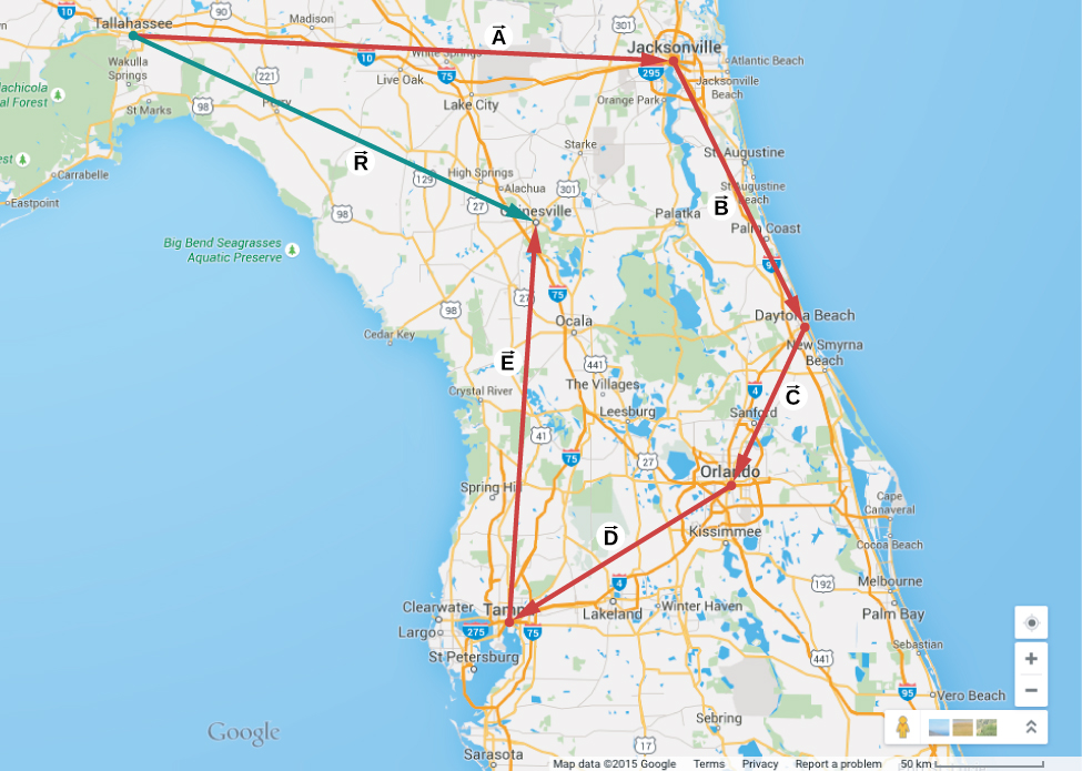
Suppose you plan a vacation trip in Florida. Departing from Tallahassee, the state capital, you plan to visit your uncle Joe in Jacksonville, see your cousin Vinny in Daytona Beach, stop for a little fun in Orlando, see a circus performance in Tampa, and visit the University of Florida in Gainesville. Your route may be represented by five displacement vectors A→, B→, C→, D→, and E→, which are indicated by the red vectors in Figure 2.11. What is your total displacement when you reach Gainesville? The total displacement is the vector sum of all five displacement vectors, which may be found by using the parallelogram rule four times. Alternatively, recall that the displacement vector has its beginning at the initial position (Tallahassee) and its end at the final position (Gainesville), so the total displacement vector can be drawn directly as an arrow connecting Tallahassee with Gainesville (see the green vector in Figure 2.11). When we use the parallelogram rule four times, the resultant R→ we obtain is exactly this green vector connecting Tallahassee with Gainesville: R→=A→+B→+C→+D→+E→.
英語のヒント
フロリダで休暇の旅行を計画しているとしよう。州都タラハシーを出発し、ジャクソンビルでおじのジョーを訪ね、デイトナビーチでいとこのヴィニーに会い、オーランドで少し遊び、タンパでサーカスを見て、ゲインズビルにあるフロリダ大学を訪れる予定である。この経路は、図2.11の赤いベクトルで示す五つの変位ベクトルA→、B→、C→、D→、E→で表せる。ゲインズビルへ着いたときの全変位は何か。全変位は五つの変位ベクトルすべての和であり、平行四辺形の法則を4回使えば求められる。別の見方として、変位ベクトルは最初の位置(タラハシー)を始点、最後の位置(ゲインズビル)を終点とすることを思い出そう。したがって、全変位ベクトルは、タラハシーとゲインズビルを結ぶ矢印として直接描ける(図2.11の緑のベクトル)。平行四辺形の法則を4回使って得る合ベクトルR→は、まさにこの緑のベクトルである。すなわち、R→=A→+B→+C→+D→+E→となる。
フロリダ州の地図に、赤いベクトルが描かれている。Aはタラハシーからジャクソンビルへ、ほぼ真西。Bはジャクソンビルからデイトナビーチへ南東。Cはデイトナビーチからオーランドへ南西。Dはオーランドからタンパへ南西(Cより水平に近い)。Eはタンパからゲインズビルへ、北から少し東寄り。タラハシーからゲインズビルへのRは緑の矢印で示される。

OpenStax / Rice University, University Physics Volume 1, CC BY 4.0. Source-book artwork retained. · CC BY 4.0 · Source出典

Figure 2.11図 2.11
When we use the parallelogram rule four times, we obtain the resultant vector R→=A→+B→+C→+D→+E→, which is the green vector connecting Tallahassee with Gainesville.
英語のヒント
平行四辺形の法則を4回使うと、合ベクトルR→=A→+B→+C→+D→+E→が得られる。これは、タラハシーとゲインズビルを結ぶ緑のベクトルである。
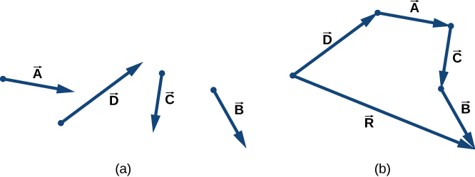
Drawing the resultant vector of many vectors can be generalized by using the following tail-to-head geometric construction. Suppose we want to draw the resultant vector R→ of four vectors A→, B→, C→, and D→ (Figure 2.12(a)). We select any one of the vectors as the first vector and make a parallel translation of a second vector to a position where the origin (“tail”) of the second vector coincides with the end (“head”) of the first vector. Then, we select a third vector and make a parallel translation of the third vector to a position where the origin of the third vector coincides with the end of the second vector. We repeat this procedure until all the vectors are in a head-to-tail arrangement like the one shown in Figure 2.12. We draw the resultant vector R→ by connecting the origin (“tail”) of the first vector with the end (“head”) of the last vector. The end of the resultant vector is at the end of the last vector. Because the addition of vectors is associative and commutative, we obtain the same resultant vector regardless of which vector we choose to be first, second, third, or fourth in this construction.
英語のヒント
多数のベクトルの合ベクトルを描く方法は、次のように尾と頭をつなぐ作図で一般化できる。四つのベクトルA→、B→、C→、D→の合ベクトルR→を描くとしよう(図2.12(a))。任意の一つを第1のベクトルに選び、第2のベクトルを、その起点(尾)が第1のベクトルの終点(頭)と一致する位置へ平行移動する。次に第3のベクトルを選び、その起点が第2のベクトルの終点と一致するよう平行移動する。図2.12のように、すべてのベクトルの頭と尾が順につながるまで、この手順を繰り返す。第1のベクトルの起点(尾)から、最後のベクトルの終点(頭)へ結んで、合ベクトルR→を描く。合ベクトルの終点は、最後のベクトルの終点にある。ベクトルの加算には結合法則と交換法則が成り立つので、どのベクトルを1番目、2番目、3番目、4番目に選んでも、同じ合ベクトルが得られる。
(a)A、B、C、Dという四つのベクトルが別々に描かれている。(b)頭と尾を順につないで配置している。Dの頭にAの尾、Aの頭にCの尾、Cの頭にBの尾がある。各ベクトルの向きは(a)と同じ。第5のベクトルRは、Dの尾からBの頭へ伸びる。

OpenStax / Rice University, University Physics Volume 1, CC BY 4.0. Source-book artwork retained. · CC BY 4.0 · Source出典

Figure 2.12図 2.12
Tail-to-head method for drawing the resultant vector R→=A→+B→+C→+D→. (a) Four vectors of different magnitudes and directions. (b) Vectors in (a) are translated to new positions where the origin (“tail”) of one vector is at the end (“head”) of another vector. The resultant vector is drawn from the origin (“tail”) of the first vector to the end (“head”) of the last vector in this arrangement.
英語のヒント
合ベクトルR→=A→+B→+C→+D→を描く、尾と頭をつなぐ方法。(a)大きさと方向が異なる四つのベクトル。(b)(a)の各ベクトルを、一つのベクトルの起点(尾)がほかのベクトルの終点(頭)に来る位置へ平行移動する。合ベクトルは、この配置の最初のベクトルの起点(尾)から、最後のベクトルの終点(頭)へ描く。
Example 2.2例題 2.2

Geometric Construction of the Resultant合ベクトルの作図

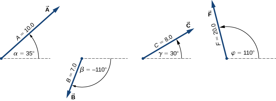
The three displacement vectors A→, B→, and C→ in Figure 2.13 are specified by their magnitudes A = 10.0, B = 7.0, and C = 8.0, respectively, and by their respective direction angles with the horizontal direction α=35°, β=−110°, and γ=30°. The physical units of the magnitudes are centimeters. Choose a convenient scale and use a ruler and a protractor to find the following vector sums: (a) R→=A→+B→, (b) D→=A→−B→, and (c) S→=A→−3B→+C→.
英語のヒント
図2.13の三つの変位ベクトルA→、B→、C→は、大きさがそれぞれA = 10.0、B = 7.0、C = 8.0で、水平方向となす方向角がそれぞれα=35°、β=−110°、γ=30°として指定されている。大きさの物理単位はセンチメートルである。適切な縮尺を選び、定規と分度器を使って、次のベクトル和を求めよ。(a)R→=A→+B→、(b)D→=A→−B→、および、(c)S→=A→−3B→+C→。
Aは大きさ10.0で、水平から反時計回りにα = 35度をなし、右上を向く。Bは大きさ7.0で、水平から時計回りにβ = −110度をなし、左下を向く。Cは大きさ8.0で、水平から反時計回りにγ = 30度をなし、右上を向く。Fは大きさ20.0で、水平から反時計回りにφ = 110度をなし、左上を向く。

OpenStax / Rice University, University Physics Volume 1, CC BY 4.0. Source-book artwork retained. · CC BY 4.0 · Source出典

Figure 2.13図 2.13
Vectors used in Example 2.2 and in the Check Your Understanding feature that follows.
英語のヒント
例題2.2と、それに続く「理解を確かめよう」で使うベクトル。

Strategy方針

In geometric construction, to find a vector means to find its magnitude and its direction angle with the horizontal direction. The strategy is to draw to scale the vectors that appear on the right-hand side of the equation and construct the resultant vector. Then, use a ruler and a protractor to read the magnitude of the resultant and the direction angle. For parts (a) and (b) we use the parallelogram rule. For (c) we use the tail-to-head method.
英語のヒント
作図でベクトルを求めるとは、その大きさと、水平方向となす方向角を求めることである。方針は、式の右辺に現れるベクトルを縮尺に従って描き、合ベクトルを作図することだ。その後、定規と分度器を使い、合ベクトルの大きさと方向角を読み取る。(a)と(b)には平行四辺形の法則、(c)には尾と頭をつなぐ方法を用いる。

Solution解答

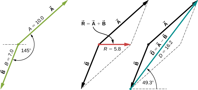
For parts (a) and (b), we attach the origin of vector B→ to the origin of vector A→, as shown in Figure 2.14, and construct a parallelogram. The shorter diagonal of this parallelogram is the sum A→+B→. The longer of the diagonals is the difference A→−B→. We use a ruler to measure the lengths of the diagonals, and a protractor to measure the angles with the horizontal. For the resultant R→, we obtain R = 5.8 cm and θR≈0°. For the difference D→, we obtain D = 16.2 cm and θD=49.3°, which are shown in Figure 2.14.
英語のヒント
(a)と(b)では、図2.14のようにベクトルB→の起点をA→の起点に合わせ、平行四辺形を作る。短いほうの対角線が和A→+B→であり、長いほうの対角線が差A→−B→である。定規で対角線の長さを測り、分度器で水平となす角を測る。合ベクトルR→についてR = 5.8 cm、θR≈0°、差D→についてD = 16.2 cm、θD=49.3°を得る。これらを図2.14に示す。
AとBを示す三つの図。AとBは尾を合わせて置かれ、Aは右上向きで大きさ10.0、Bは左下向きで大きさ7.0。両者のなす角は145度。第2図では、平行四辺形を完成させる破線が加わる。和R = A + Bは、AとBの尾から向かいの頂点へ伸び、大きさ5.8。第3図にも平行四辺形の破線があり、差D = A − BはBの頭からAの頭へ伸びる。大きさ16.2で、水平となす角49.3度。第2図のRは、第3図のDよりかなり短い。

OpenStax / Rice University, University Physics Volume 1, CC BY 4.0. Source-book artwork retained. · CC BY 4.0 · Source出典

Figure 2.14図 2.14
Using the parallelogram rule to solve (a) (finding the resultant, red) and (b) (finding the difference, blue).
英語のヒント
平行四辺形の法則を使った、(a)合ベクトル(赤)の作図と、(b)差のベクトル(青)の作図。
For (c), we can start with vector −3B→ and draw the remaining vectors tail-to-head as shown in Figure 2.15. In vector addition, the order in which we draw the vectors is unimportant, but drawing the vectors to scale is very important. Next, we draw vector S→ from the origin of the first vector to the end of the last vector and place the arrowhead at the end of S→. We use a ruler to measure the length of S→, and find that its magnitude is
S = 36.9 cm. We use a protractor and find that its direction angle is θS=52.9°. This solution is shown in Figure 2.15.
英語のヒント
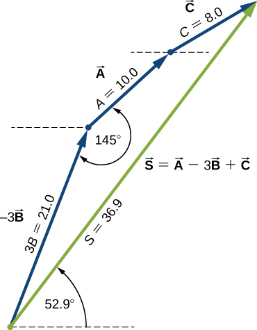
(c)では、ベクトル−3B→から始め、図2.15のように残りのベクトルの尾と頭を順につなげて描ける。ベクトルの加算では、描く順序は重要でないが、縮尺に従って描くことは非常に重要である。次に、最初のベクトルの起点から最後のベクトルの終点へ、ベクトルS→を描き、S→の終点に矢じりを付ける。定規でS→の長さを測ると、大きさはS = 36.9 cmとわかる。分度器で測ると、方向角はθS=52.9°とわかる。この解を図2.15に示す。
青い三つのベクトルの頭と尾が順につながっている。−3Bは右上向きで、大きさ3B = 21.0。AはBの頭から右上へ伸び、大きさ10.0。Aと−3Bのなす角は145度。CはAの頭から伸び、大きさ8.0。緑のSは−3Bの尾からCの頭へ伸びる。S = A − 3B + Cで、大きさ36.9、水平から反時計回りに52.9度をなす。

OpenStax / Rice University, University Physics Volume 1, CC BY 4.0. Source-book artwork retained. · CC BY 4.0 · Source出典

Figure 2.15図 2.15
Using the tail-to-head method to solve (c) (finding vector S→, green).
英語のヒント
尾と頭をつなぐ方法による(c)の解。ベクトルS→(緑)を求める。
Additional Resources追加教材