第10章固定軸まわりの回転
Calculating Net Torque for Rigid Bodies on a Fixed Axis固定軸を持つ剛体の合トルクの計算
In the following examples, we calculate the torque both abstractly and as applied to a rigid body.
英語のヒント
以下の例では、抽象的な場合と、剛体に力が加わる場合の両方でトルクを計算する。
We first introduce a problem-solving strategy.
英語のヒント
まず、問題を解くための方針を示す。
Example 10.14例題 10.14
Calculating Torqueトルクの計算
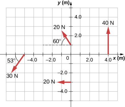
Four forces are shown in Figure 10.34 at particular locations and orientations with respect to a given xy-coordinate system. Find the torque due to each force about the origin, then use your results to find the net torque about the origin.
英語のヒント
図10.34には、与えられたxy座標系に対して特定の位置と向きを持つ四つの力を示している。各力による原点の周りのトルクを求め、その結果から原点の周りの合トルクを求めよ。
OpenStax / Rice University, University Physics Volume 1, CC BY 4.0. Source-book artwork retained. · CC BY 4.0 · Source出典

Figure 10.34図 10.34
Four forces producing torques.
英語のヒント
トルクを生む四つの力。
Strategy方針
This problem requires calculating torque. All known quantities––forces with directions and lever arms––are given in the figure. The goal is to find each individual torque and the net torque by summing the individual torques. Be careful to assign the correct sign to each torque by using the cross product of and the force vector .
英語のヒント
この問題ではトルクを計算する。既知の量、すなわち向きも含めた力と腕の長さは、すべて図に示されている。目標は、個々のトルクと、それらを加えた合トルクを求めることである。と力のベクトルの外積を使い、各トルクに正しい符号を付けるよう注意する。
Solution解答
Use to find the magnitude and to determine the sign of the torque.
英語のヒント
から大きさを求め、からトルクの符号を決める。
The magnitude of the torque from force 40 N in the first quadrant is given by .
英語のヒント
第1象限にある40 Nの力によるトルクの大きさは、となる。
The cross product of and is out of the page, positive.
英語のヒント
との外積は紙面から手前へ向くので、正である。
The magnitude of the torque from force 20 N in the third quadrant is given by.
英語のヒント
第3象限にある20 Nの力によるトルクの大きさは、となる。
The cross product of and is into the page, so it is negative: .
英語のヒント
との外積は紙面の奥へ向くので、負のとなる。
The magnitude of the torque from force 30 N in the third quadrant is given by .
英語のヒント
第3象限にある30 Nの力によるトルクの大きさは、となる。
The cross product of and is out of the page, positive.
英語のヒント
との外積は紙面から手前へ向くので、正である。
The magnitude of the torque from force 20 N in the second quadrant is given by .
英語のヒント
第2象限にある20 Nの力によるトルクの大きさは、となる。
The cross product of and is out of the page.
英語のヒント
との外積は紙面から手前へ向く。
The net magnitude of the torque is therefore
英語のヒント
したがって、合トルクの大きさはとなる。
Significance考察
Note that each force that acts in the counterclockwise direction has a positive torque, whereas each force that acts in the clockwise direction has a negative torque. The torque is greater when the distance, force, or perpendicular components are greater.
英語のヒント
反時計回りに作用する力はそれぞれ正のトルクを生み、時計回りに作用する力はそれぞれ負のトルクを生む。距離、力、または垂直成分が大きいほど、トルクは大きくなる。
Example 10.15例題 10.15
Calculating Torque on a rigid body剛体に働くトルクの計算
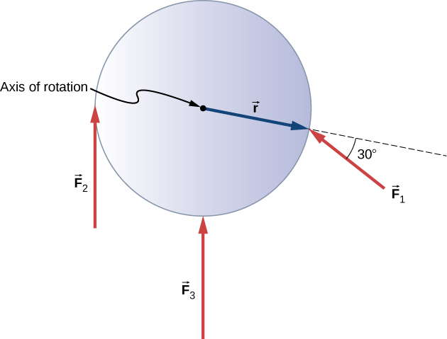
Figure 10.35 shows several forces acting at different locations and angles on a flywheel. We have , , and . Find the net torque on the flywheel about an axis through the center.
英語のヒント
図10.35には、はずみ車の異なる位置に異なる角度で働くいくつかの力を示している。 、、である。中心を通る軸の周りの、はずみ車に働く合トルクを求めよ。
OpenStax / Rice University, University Physics Volume 1, CC BY 4.0. Source-book artwork retained. · CC BY 4.0 · Source出典

Figure 10.35図 10.35
Three forces acting on a flywheel.
英語のヒント
はずみ車に働く三つの力。
Strategy方針
We calculate each torque individually, using the cross product, and determine the sign of the torque. Then we sum the torques to find the net torque.
英語のヒント
外積を使って各トルクを個別に計算し、その符号を求める。その後、トルクを加え合わせて合トルクを求める。
Solution解答
We start with . If we look at Figure 10.35, we see that makes an angle of with the radius vector . Taking the cross product, we see that it is out of the page and so is positive. We also see this from calculating its magnitude:
英語のヒント
から始める。図10.35を見ると、は半径ベクトルとの角をなす。外積を取ると、その向きは紙面から手前へ向くので正である。これは、大きさを計算しても分かる。
Next we look at . The angle between and is and the cross product is into the page so the torque is negative. Its value is
英語のヒント
次にを見る。との間の角はで、外積は紙面の奥へ向くのでトルクは負となる。その値は次のとおりである。
When we evaluate the torque due to , we see that the angle it makes with is zero so Therefore, does not produce any torque on the flywheel.
英語のヒント
によるトルクを計算すると、この力との間の角は0なので、となる。したがって、は、はずみ車にトルクを生じさせない。
We evaluate the sum of the torques:
英語のヒント
トルクの和を計算する。
Significance考察
The axis of rotation is at the center of mass of the flywheel. Since the flywheel is on a fixed axis, it is not free to translate. If it were on a frictionless surface and not fixed in place, would cause the flywheel to translate, as well as . Its motion would be a combination of translation and rotation.
英語のヒント
回転軸は、はずみ車の質量中心にある。はずみ車は固定軸に取り付けられているので、自由に並進することはできない。摩擦のない面上にあり、位置が固定されていなければ、はと同じく、はずみ車を並進させる。その運動は、並進と回転を組み合わせたものになる。